MPLS - The Core of
Modern Networking.
Evolution, Mechanics, and Architecture of Service Provider Networks.
Integrated Video: MPLS Introduction
Evolution of SP Architectures
Traditional vs. Modern Service Providers
Historically, network services were divided between two distinct entities:
- Traditional ISPs: Primary focus was providing Internet access.
- Traditional Telcos: Primary focus was providing Virtual Private Networks (VPNs) and telephony.
Modern Service Providers have transitioned to a unified, IP-based infrastructure. By utilizing MPLS, they maintain a single technology stack to support a diverse array of services, including:
- Internet access and Virtual Private Networks.
- Telephony and Video services.
- Cloud and Managed services.
- Stringent Quality of Service (QoS).
Cisco IP NGN Architecture
The Cisco IP Next-Generation Network (NGN) is an all-IP architecture designed for video,
mobile, and cloud services. It is organized into three primary layers:
- Application Layer: Where specific software services reside.
- Services Layer: Manages mobile, cloud, and video offerings.
- IP Infrastructure Layer: Provides connectivity between the customer and the service provider. This layer includes access, aggregation, IP edge (where PE routers reside), and the core (where P routers reside).
Supporting Technologies: Optical & Ethernet
Optical Networking (SONET/SDH and DWDM)
Modern cores utilize Wavelength Division Multiplexing (WDM) to increase bandwidth.
- SONET/SDH: Traditional synchronous transport modules (STM) and signals (STS). For example, STM-64/STS-192 operates at approximately 10 Gb/s.
- DWDM and ROADM: Reconfigurable Optical Add/Drop Multiplexers (ROADM) allow for flexible optical networking.
- IP over DWDM (IPoDWDM): This evolution eliminates the need for Optical-Electrical-Optical (O-E-O) conversion by using integrated transponders, allowing routers to interface directly with the optical layer.
Gigabit Ethernet Standards
Ethernet has largely replaced ATM and SDH in the service provider environment. The 10/40/100
Gigabit Ethernet standards share key characteristics:
- Support for full-duplex operation only.
- Preservation of the 802.3 MAC and frame formats (including min/max sizes).
- Bit Error Rate (BER) better than or equal to 10-12.
- Support for Optical Transport Network (OTN).
The Mechanics of MPLS
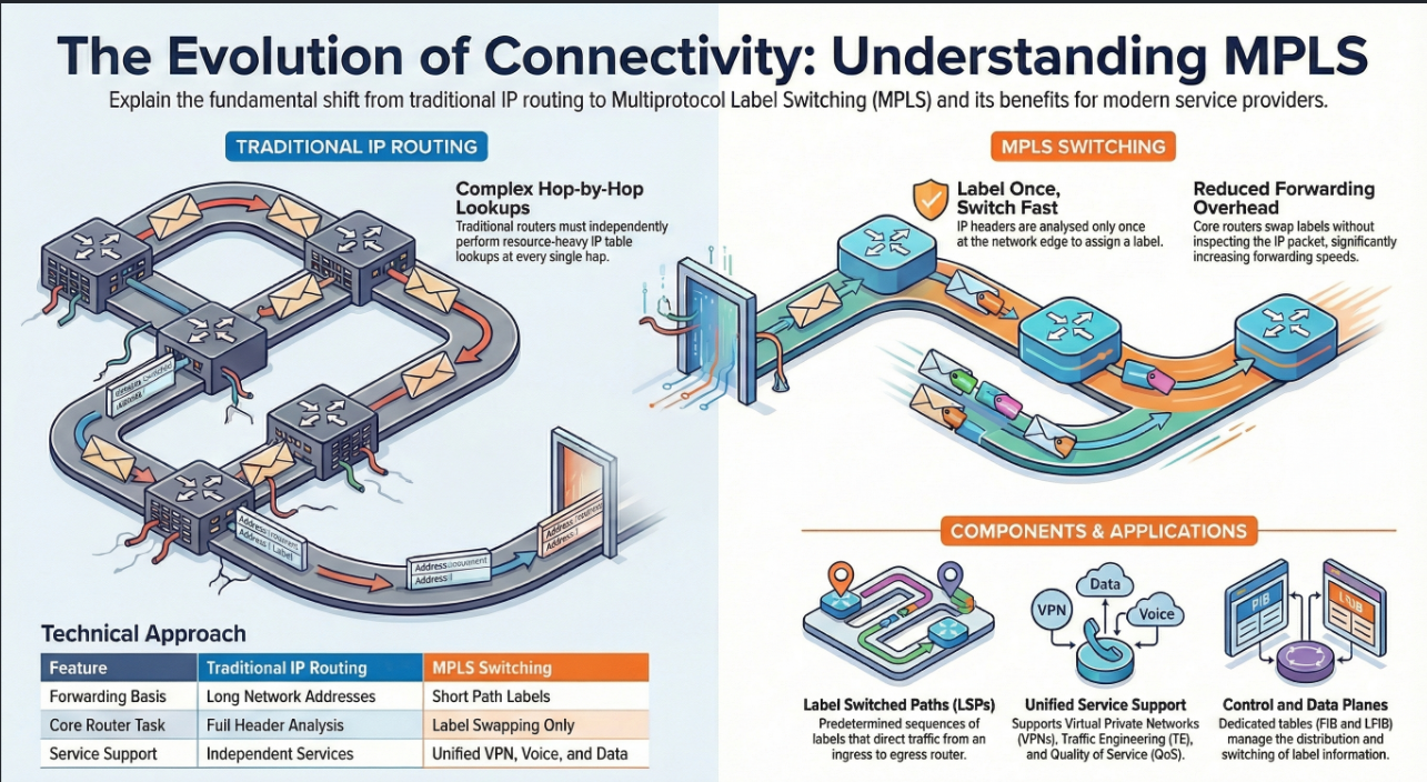
Traditional Routing vs. MPLS Switching
In traditional IP routing, every router in the path performs an independent Layer 3 lookup
based on the destination IP address, the local routing table, and the packet header.
MPLS enhances this by basing forwarding decisions on short path labels rather than long
network addresses.
- Edge Lookup: Only routers at the edge of the MPLS domain perform a full routing lookup.
- Label Switching: Once a packet enters the domain, it is forwarded based on the MPLS label. This reduces the forwarding overhead on core routers because intermediate routers do not analyze the IP packet.
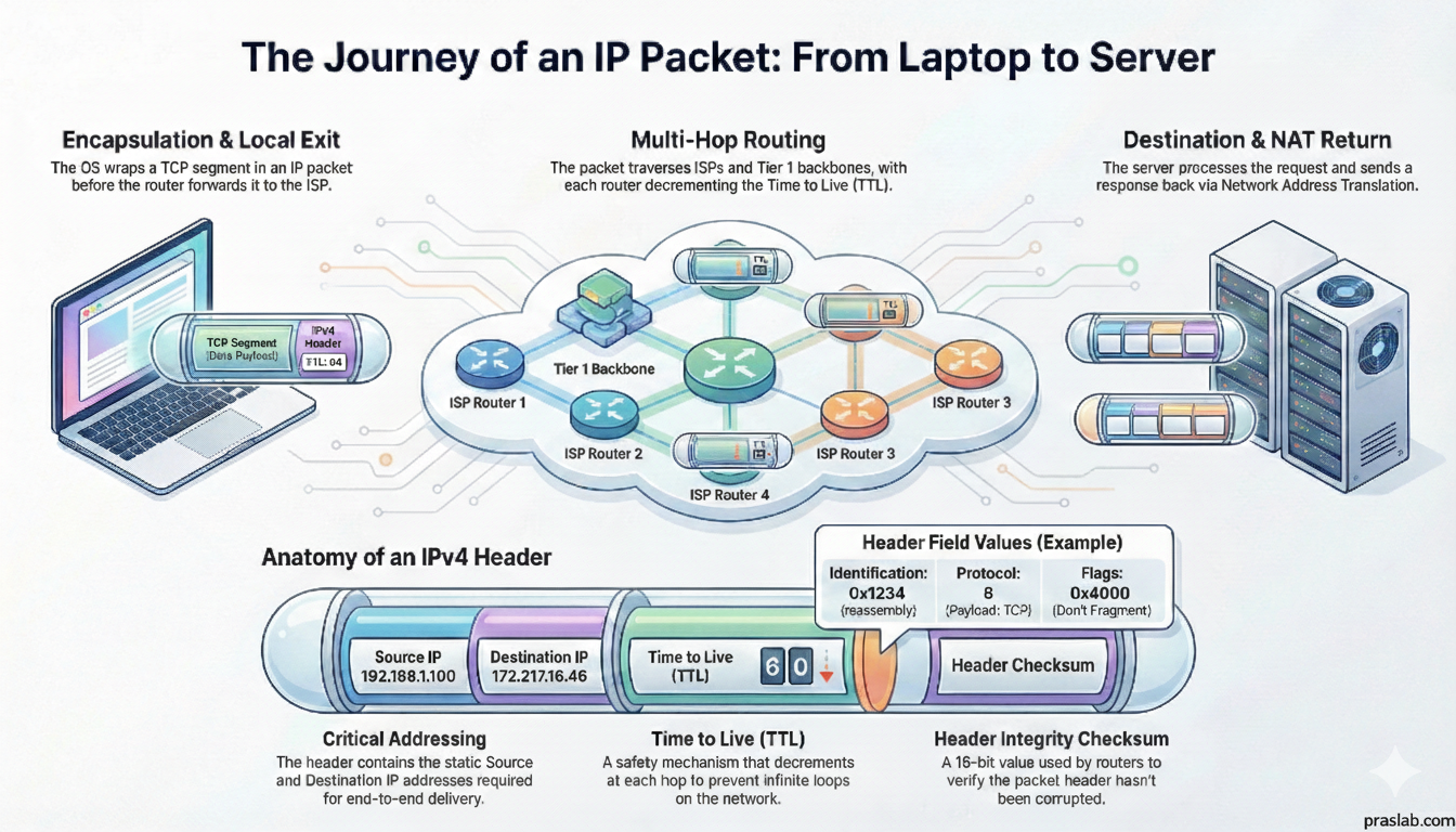
The MPLS Label Structure
The MPLS header is an intermediate encapsulation between Layer 2 and Layer 3. It consists
of:
- Label (20 bits): The value used for switching.
- Experimental (EXP) Field (3 bits): Often used for Quality of Service (QoS).
- Bottom-of-Stack Indicator (1 bit): Identifies if the label is the last one in the stack.
- Time to Live (TTL) (8 bits): Prevents infinite loops.
Router Roles and the Label Switched Path (LSP)
A predetermined path through an MPLS network is called a Label Switched Path (LSP). Routers
within an LSP take on specific roles:
- Ingress Router (Edge LSR): The start of the LSP. It imposes (pushes) a label onto incoming IP packets.
- Transit Router (LSR): Intermediate routers that switch labeled packets. An LSP can have up to 253 transit routers.
- Egress Router (Edge LSR): The end of the LSP. It removes (pops) the label and forwards the original IP packet to its destination.
Control and Data Planes
- Control Plane: Uses protocols like OSPF and the Label Distribution Protocol (LDP) to exchange routing information and distribute labels. This builds the Routing Information Base (RIB).
- Data Plane: Responsible for the actual forwarding of packets. It uses the Forwarding Information Base (FIB) for IP packets and the Label Forwarding Information Base (LFIB) for labeled packets.
Short Answer Quiz
- How does a modern service provider differ from a traditional ISP or Telco?
- What is the primary benefit of IPoDWDM in a service provider network?
- Explain the difference between how traditional IP routing and MPLS handle packet forwarding at each hop.
- Describe the three components of the Cisco IP NGN architecture.
- What are the four primary applications supported by MPLS in a service provider environment?
- What specific functions does an Edge LSR perform at the entry and exit points of an MPLS domain?
- What information is contained within the 32-bit MPLS label header?
- Explain the roles of the Ingress and Egress routers within a Label Switched Path (LSP).
- What are the requirements for the 40/100 Gigabit Ethernet standards regarding frame format and data rates?
- How do the Control Plane and Data Plane interact within a Label Switch Router (LSR)?
Answer Key
1. Modern vs Traditional: While traditional ISPs focused on Internet and Telcos focused on VPNs, a modern service provider uses a unified IP-based infrastructure. By utilizing MPLS, they can support Internet, VPNs, telephony, and video services on a single technology stack.
2. IPoDWDM Benefit: IPoDWDM integrates transponders directly into the routing equipment, allowing for "No O-E-O" (Optical-Electrical-Optical) conversion. This simplifies the architecture by allowing routers to communicate directly over the DWDM layer.
3. Routing vs MPLS: Traditional IP routing requires every router in a path to perform a complex Layer 3 lookup based on the destination IP and local routing table. In contrast, MPLS performs a routing lookup only at the edge, while intermediate routers forward packets based on short, fixed-length labels.
4. Cisco IP NGN: The Cisco IP NGN architecture consists of the Application Layer, the Services Layer (handling mobile, cloud, and video), and the IP Infrastructure Layer (access, aggregation, edge, and core).
5. MPLS Applications: MPLS supports Unicast and Multicast IP routing, Virtual Private Networks (VPNs), Traffic Engineering (TE), and Quality of Service (QoS).
6. Edge LSR Functions: At Ingress, the Edge LSR performs a routing lookup, imposes an MPLS label, and forwards. At Egress, it removes the MPLS label and forwards the original IP packet.
7. Label Header: The header includes a 20-bit label used for switching, a 3-bit experimental field typically used for QoS, a 1-bit bottom-of-stack indicator, and an 8-bit TTL field.
8. Ingress/Egress Roles: The Ingress router encapsulates standard IP packets with an MPLS header to begin the path. The Egress router acts as the final stop, stripping the label to return the packet to its IP format.
9. Ethernet Standards: These standards must support a MAC data rate of 40/100 Gb/s while preserving the traditional 802.3 Ethernet frame format. They only support full-duplex operation and must maintain a BER of 10^-12.
10. Control/Data Plane: The Control Plane uses protocols like OSPF and LDP to exchange routing information and build the RIB. The Data Plane uses this to populate the FIB and LFIB to forward packets.
Essay Questions
- The Evolution of the Core: Discuss the transition from ATM and SDH-based cores to the modern IP+MPLS core, highlighting why this transformation was necessary for modern service providers.
- MPLS as a Performance Multiplier: Analyze how MPLS reduces forwarding overhead and improves network speed compared to traditional hop-by-hop IP routing.
- The Role of Optical Innovation: Explain the significance of DWDM, ROADM, and IPoDWDM in scaling service provider bandwidth and reducing hardware complexity.
- Comprehensive Service Delivery: Describe how the Cisco IP NGN architecture enables a service provider to deliver video, mobile, and cloud services over a unified infrastructure.
- Traffic Management in MPLS: Explore how the features of MPLS, such as Traffic Engineering (TE) and the experimental field in the label, allow providers to manage network congestion and ensure Quality of Service.
DWDM
Dense Wavelength Division Multiplexing. Increases fiber capacity by multiplexing multiple optical signals onto a single fiber using different wavelengths.
Edge LSR
A router located at the boundary of an MPLS network that either adds (imposes) labels to incoming traffic or removes (pops) labels from outgoing traffic.
FIB
Forwarding Information Base. A table used by the data plane to make destination-based switching decisions for IP packets.
LDP
Label Distribution Protocol. A control plane protocol used by LSRs to exchange label mapping information.
LFIB
Label Forwarding Information Base. A table used by the data plane in an MPLS-enabled router to forward labeled packets.
LSP
Label Switched Path. A specific, predetermined path that a labeled packet follows through an MPLS network.
LSR
Label Switch Router. Any router capable of forwarding packets based on MPLS labels.
MPLS
Multiprotocol Label Switching. A high-performance telecommunications mechanism that directs data based on short path labels rather than long network addresses.
ROADM
Reconfigurable Optical Add/Drop Multiplexer. A device that allows for the remote and flexible switching of wavelengths in a DWDM network.
SONET/SDH
Standards for synchronous data transmission over optical fiber; SONET is used in North America while SDH is used internationally.